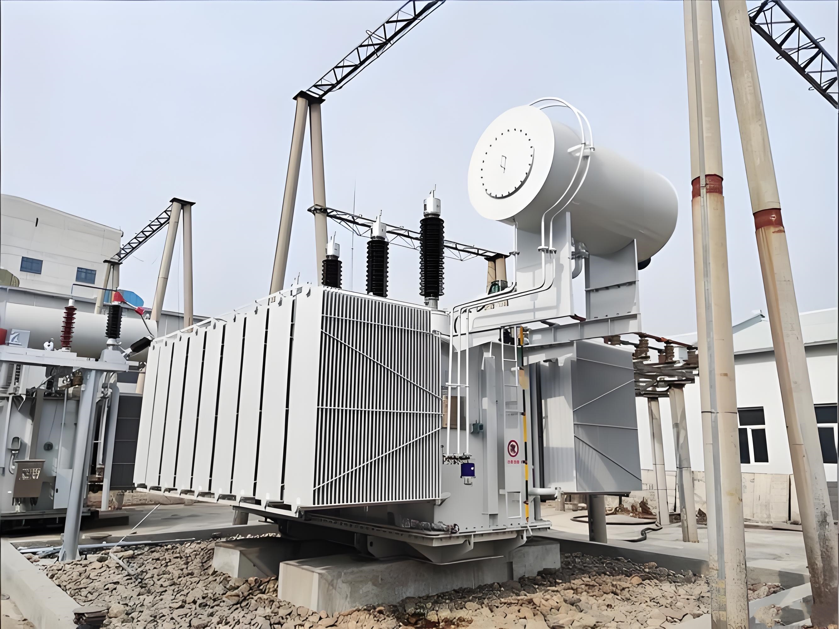
On load tap changer (OLTC) is a type of transformer that can complete tap voltage switching during load operation. It can adjust the tap position of the transformer to maintain voltage stability and ensure power supply quality when the system voltage fluctuates or the user load changes.
Brand Name:CLHT
Tap Gear:5/9/11/15
Phase:Three
Service Voltage:11KV/33KV
Email:clhtee@hnclht.com
Tel/WhatsApp:8619937686750
On load tap changer transformer(OLTC) is a type of transformer that can complete tap voltage switching during load operation. It can adjust the tap position of the transformer to maintain voltage stability and ensure power supply quality when the system voltage fluctuates or the user load changes.
Its core lies in achieving a smooth transition of the tap without interrupting the load current. This process is completed by two key subsystems working together: tap selectors and toggle switches, and relies on transition resistors to suppress circulating currents.
1. Pre operation inspection: Confirm that the transformer is operating normally, the tap changer position is correct, and the instrument indication is normal.
2. Adjust the tap changer: According to the voltage demand, slowly rotate the tap changer handle in the order of operation, and observe the voltage change after each gear is switched.
3. Post operation inspection: Check the position of the tap changer, inspect the transformer for any abnormalities, and record the operation process.
1. Manual mode: Operate step by step through the local handle or electric mechanism, with a minimum interval of 1 minute between each gear switch. Cross gear operation is strictly prohibited.
2. Automatic mode: The voltage monitoring relay collects the secondary voltage in real time. When the deviation exceeds the set threshold (such as ± 2%), the control logic unit is triggered to automatically perform upshift/downshift operations.
Attention: The advanced system adopts a fuzzy logic controller (FLC) to dynamically make decisions based on voltage trends and load change rates, reducing unnecessary frequent switching and extending equipment life.
1. Pre selection stage (selector action)
In the case of continuous flow of load current, the tap selector first pre selects the target tap to be connected to the circuit under the condition of no current passing through. At this stage, only the "positioning" of the electrical path is completed, without involving the switching of the main current, so no arc is generated.
2. Switching phase (switch action)
The toggle switch instantly operates near the zero crossing of the current, bridging the main load current from the original tap to the pre selected tap. During this transition period, two taps are connected in parallel through a transition resistor to form a current branch, effectively limiting the circulating current caused by voltage differences (usually 5%~10% of the rated current), and avoiding short circuits and arc damage.
Key principle: The switching process is essentially "bridging first, then disconnecting" to ensure current continuity; Transition resistance is the technical cornerstone for achieving "load switching".
IEC 60214-2 and GB/T 6451 explicitly require:
1. Switching timing: transition time ≤ 25ms, contact synchronization error ≤ 5ms;
2. Deviation of transition resistance value ≤ ± 10%;
3. Oil sample breakdown voltage testing (≥ 40kV) must be conducted every 2000-4000 operations;
4. It is prohibited to adjust the voltage when the load exceeds 115% of the rated value;
5. Parallel operation of transformers must be synchronized or alternately regulated, and continuous operation of a single unit is prohibited.